SMD Circuit Board Design
April 2026
For the power supply, I used standard 1.5 volt batteries. In order to create a 3 volts supply for the circuit board, I put two of the DURACELL batteries into a battery holder to combine them.
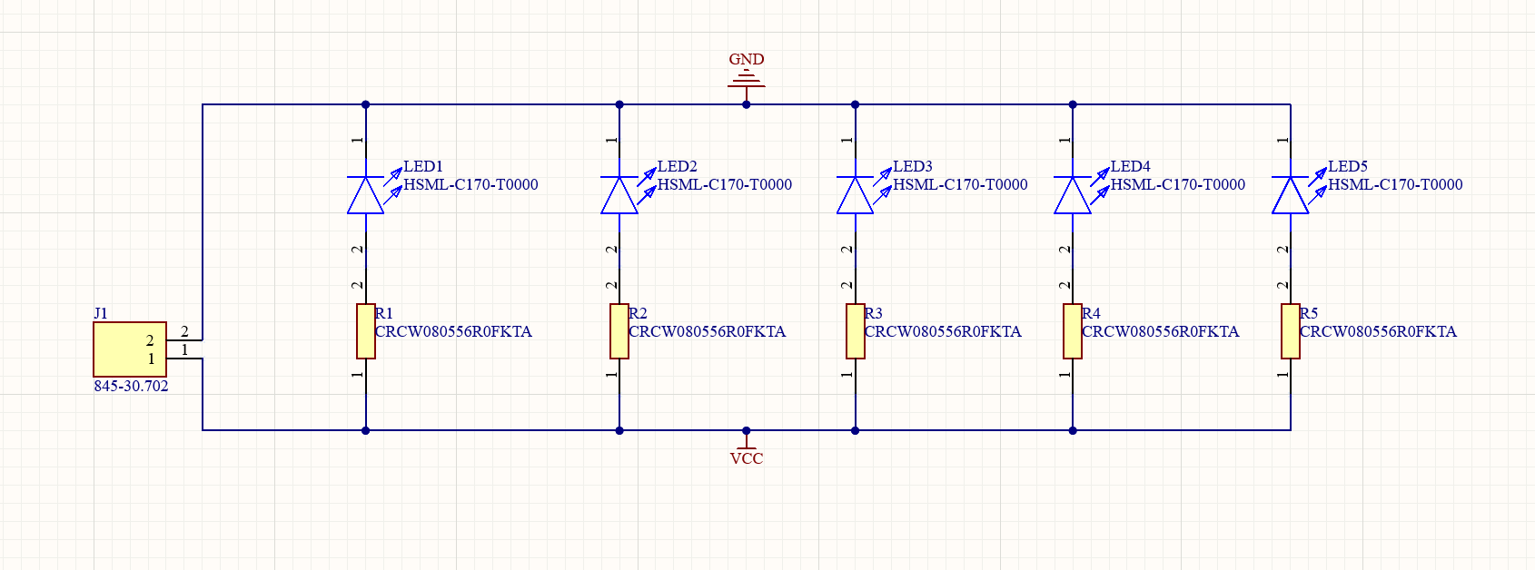
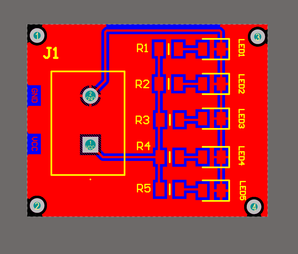
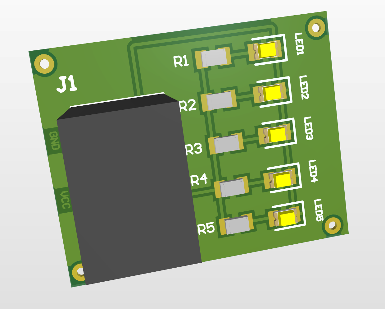
Ordered some SMD (surface mount device) type LEDs for this project though a supplier website which is Mouser Electronics. SMDs are way tinier than regular LEDs that are used in the lab. However, they can generate good amount of light and keep the circuit board small size. Chose HSML-C170-T0000 because it has PCB Footprint and symbol. Forward voltage is at 1.9V which is less than our combined 3V supply.
Connecting them in parallel so that each of LED receives the same voltage. However, they will be destroyed with the 3V supply without any resistors. Too much current flowing through will burn the LEDs and we need a resistor before in front of the LED to limit the current and remove excess voltage (about 1.1V must be removed).
Resistance = Voltage / Current
20mA for each LED, so 1.1V / 20mA will be equal to 55 ohm resistance.
Ordered some resistors from Mouser for each of the LED, which has 56 ohms and tolerance of 1%